After seeing photos of turnings that were taken at close range from a vantage point slightly above the pieces - and then seeing the ACTUAL pieces - what I saw in person was quite different from what I saw in photos. So,I've been wondering why?
We are told that the PROFILE of a turning is very important. And we are told that PROPORTIONS are also very important. So we often work our the proportions and profile with pencil and paper and maybe use a ruler. We DESIGN in 2D in SIDE VIEW (or if you prefer FRONT VIEW). We DESIGN with LINES that enclose an AREA - on a flat 2D PLANE (a piece of paper). WHAT we TURN are SURFACES of a VOLUME in 3D SPACE.
We then turn the piece ON ITS SIDE.
We PHOTOGRAPH the piece standing upright - not in a true FRONT VIEW - but from slightly above the piece so we can see a little of the top of the piece.
However, when the piece is actually displayed, it's seldom displayed so that the viewer sees any of the views used in designing, turning or photographing the piece. From a distance, a viewer may see the profile in FRONT or SIDE VIEW, but usually from far enough away so as to not being able to see details of the piece. When close enough to the piece to see the details, the viewer is too close to see the DESIGNED FRONT / SIDE VIEW PROFILE. Unless viewer crouches down or kneel, they probaly won't be ableto see the DESIGNED FRONT / SIDE VIEW - AND - the DETAILS - at the same time. See one OR the other, but not both AT THE SAME TIME.
HOW you SEE affects WHAT you PERCEIVE.
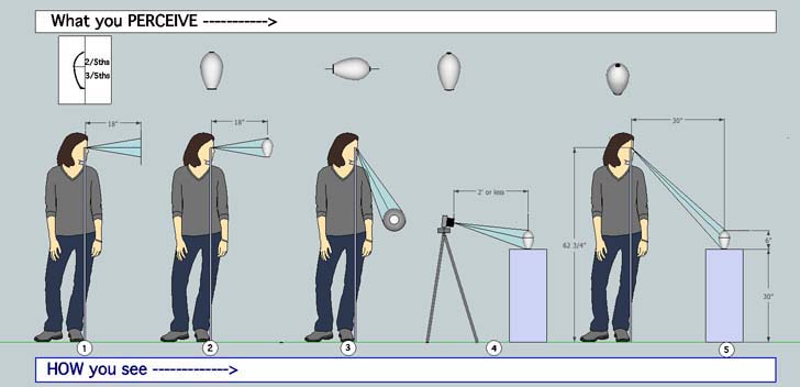
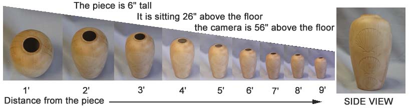
Here's an example of what I'm talking about. Notice that the farther away from the piece you are, the closer what you see looks like the profile designed in SIDE VIEW. But, the farther you are from the piece, the less details can be seen. This example piece has laser low relief carved fan shells on the front. From four feet or more away from thepiece, the carvings are barely noticable, if seen at all. Also notice that the closer you get to the piece, the more details are visible - but the designed profile that you worked on so hard to design - is no longer visible.
WHAT IF . . .
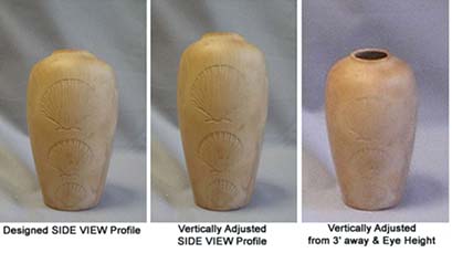
You could start with a 2D side view drawing of a nice form with good proportions - and then adjust only the vertical proportions - so that when the actual piece is viewed from normal eye height from about 2 to 3 feet away, what you'd see was very similar to your original designed in side view profile - AND you'd be close enough to see the details of the piece?
Here's an example of this idea.
THAT is what this article is about - how to calculate the VERTICAL ADJUSTMENT FACTOR (VAF) for a tall hollow form that you initially designed on paper - in Side View.
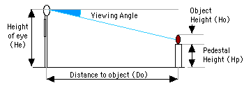
So let's look at what we're playing with - How We See - What We Perceive
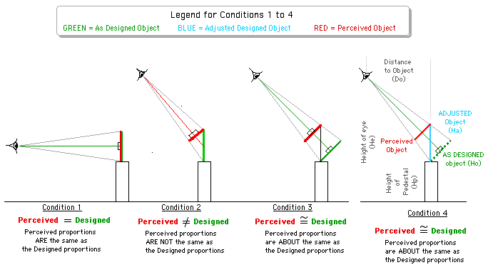
Condition 1 is how we design the proportions of the profile of a piece.
Condition 2 is how th piece is normally viewed - standing upright and viewed from above at some distance from the piece.
Condition 3 is how you'd need to display the piece in order to have the viewer see the Designed Profile. NOT very practical!
Condition 4 Vertically Adjusts the original design proportions of the profile so that is what's seen (pereceived) when viewed as pieces are normally seen is very similar to that of the orignal designed profile.
Condtion 4 looks promising. But can we work out a way to calculate the Height of the ADJUSTED Object?
There IS a way to calculate how tall the ADJUSTED piece should be to meet Condition 4.
To numerically calculate - you need numbers (DUH!) to start with - your Viewing Parameters.
You need to know, or assume, the following
- the eye height of the viewer (He)
- the optimum distance to your object / piece where the viewer is close enough to see most details of the piece -
. and still be able to see your orignal designed profile (Do)
- the height of your Original Design Height (Ho)
- the height of the pedestal or table top the piece will be displayed on (Hp)
Depending on your data source, the average U.S. male height is 5' 9 1/2", and the average U.S. female height is 5'4". So if you average the averages ( [69.5 + 64] / 2 ) you get an average "average height" of 66 3/4". If you assume that the distance from top of head to eyes is about 4" - then the Height of Eyes (He) = 62.75" (66 3/4" - 4").
Now the average table height is 30", so lets assume that will be the Display Height. So make Hp = 30"
You can measure the height of your piece,object from your full scale 2D Side View Design. Let's say it's 6" tall. So Ho = 6".
All we need now is the horizontal distance between the viewers eyes and the vertical centerline of your piece (Do). The viewer has to be close enough to see some or most of the details of the piece - but not looking almost straight down on the piece. That happens when the viewer is between two and three feet from the piece (unless the piece is very tall). Since most tall hollow forms are in the 6" to 12" range, we'll go with the low end of the range and we'll average the 2 - 3' range. So Do = 30"
So here are the parameter values for our calculaltions
He = 62.75"
Ho = 6"
Hp = 30"
Do = 30"
With a little Trig and a bit of Geometry we can come up with the VERTICAL ADJUSTMENT FACTOR VAF (Relax, you won't have to do any of the math, I'll be providing a spreadsheet that does all the work. You plug in your parameter values and it calculate the VAF for you and shows it in RED so you can't miss it).
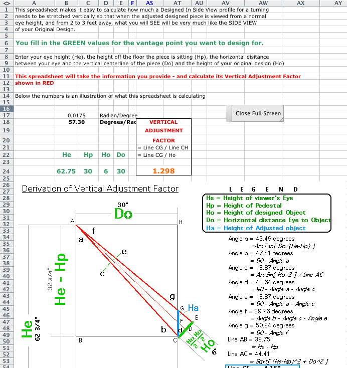
For the Math Phreaks, here's how the VAF is calculated, with numeric results of intermediary calculations for a specific example - the one with the parameter values given above and shown in this illustration.
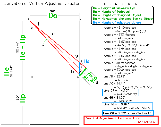
To check my math, I created a virtual model at 1:1 scale of the conditions shown in the above illustration. With that 1:1 virtual 3D scale model, I could measure the angles and line lengths I'd calculate - to 0.1 degrees and 1/64th inch accuracy. The calculated angles were within + 0.01 and - 0.06 degrees of the angles measured in the virtual 1:1 scale 3D model. The calculated line lengths were within + 0.00 and - 0.01 inches. As a former surveyor, I'd say that was "close enough for sewerline" precision ; )
OK - so once you have the Vertical Adjustment Factor, you can go back to your Original Design Proportions and Profile, get a blank piece of paper and with a bit of measuring off your Original, it ain't that hard to draw the Adjusted Design. You know how tall the piece needs to be and you hopefully know, have some idea, or can measure where your Curve Transitions are. For the Example Piece I've been using for my examples, the "shoulder" of the 6" tall hollow form was 3/5ths of the height - up from the bottom (or 2/5ths of the height down from the top). So the shoulder for the adjusted 7 3/4" tall Adjusted Design should be about 3 1/8" down from the top (or about 4 5/8" up from the bottom). The Horizontal proportions remain unchanged.
The limitation of adjusting the design proportions and profile - in 2D on paper - is that you can't SEE what the adjusted piece will look like when viewed from normal eye height, from 2 to 3 feet away - looking down on it - unless you actually turn the Adjusted Piece.
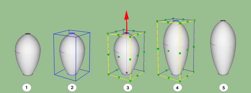
AH - that's were 3D modeling comes in. Scaling a virtual 3D object is pretty quick and easy. Here's how easy it is to stretch a Google SketchUp virtual 3D model of the designed object - just vertically. (1) is the Original Design, (2)is the Original Design "selected" as indicated by the blue box around it (3) the green "handles" can be selected to "stretch" the object in a lot of different directions - we only want to stretch our model VERTICALLY. Once you selected the "stretch direction", you can enter by how much you want to stretch it numerically. In our example case we want to stretch it vertically by 1.298. (4) is what your model looks like in SIDE VIEW after being stretched - still with a box and green "handles" around it. (5) is the stretched model - without the distracting Box and Handles around it.
I could have applied this stretching method to the Orignal Design's Profile, then rotate that adjusted profile to generate the virtual 3D form shown above in (5).
The cool thing about designing in a virtual 3D modeling environment is - that you can then SEE what the adjusted piece looks like - when viewed from normal eye height and from a typical viewing distance, or for any other vantage point conditions. Not only that, but you can compare that view - with your original design.
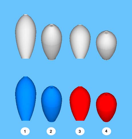
Let me show you what I mean. In the illustration below, two views of the Adjusted Design (the BLUE forms on the left), and two views of the Original Design (the RED forms on the right) are shown for visual comparisons. For the BLUE form, the SIDE VIEW is to the left (1), the As Normally Viewed is to the right (2). Notice how similar the two center forms appear (2) & (3). Notice how DIFFERENT the As Normally Viewed are to their SIDE VIEW version (2) & (1) and (4) & (3).
By now, I hope I've got you considering trying this idea. And I suspect that it's ALL THAT MATH and all that CALCULATING that makes you hesitant to actually try this idea.
RELAX, I've already done the math and created a spreadsheet you can download, plug in the viewing variables you want to use - and it'll calculate the Vertical Adjustment Factor and show you it in RED - in a BOLD FONT.
Here's a screen capture of what the spreadsheet looks like - or at least the part you'll SEE. I couldn't get ALL of the spreadsheet on one screen so the bottom illustration has been cut off at the bottom. You've already seen it earlier, if you started at the top of this web page. There are a bunch of columns that do the calculations - that are hidden since you probably aren't interested in the formulas and things like converting Radians to Degrees or Degrees to Radians, and probably don't like Trig or Geometry ; )
TO DOWNLOAD THE EXCEL SPREADSHEET, IN .XLS FILE FORMAT - CLICK HERE
If you have questions or comments about this info or have suggestions to make it clearer and easier to understand please e-mail me