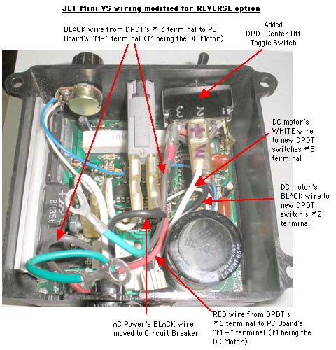
Adding REVERSE to the JET Mini VS Lathe
The JET Mini VS is a great little lathe. But it doesn't have the REVERSE feature found on more expensive lathes. REVERSE can come in handy when sanding - and when holllowing. It was hollowing that got me looking into a way to REVERSE my JET Mini. My back doesn't like having to lean over the lathe bed while hollowing. Sure, I COULD turn from the back of the lathe - except for the fact that I have lights and a dust hood back there.
So I went searching for a way to add REVERSE to my JET Mini VS and found a great start in a WoodCentral turning forum thread on the subject and a link to a PDF version of a How To article (link to that thread). The key to adding reverse was a DPDT switch (Double Pole, Double Throw). That gave me Part 1 of what I needed to know. A DPDT switch would let me reverse the polarity of the current gong to the JET's DC motor. But the method for adding a separate external switch box meant driling a hole in the side of the JET's controller box where there's not much room. I started down that road and quickly discovered that working with a bunch of wires in a small plastic box wasn't much fun.
But while at Radio Shack looking for a DPDT switch, paddle connectors and wire - I found a DPDT Center OFF toggle switch rated at 10 Amps - and it was the same size as the toggle switch on my JET - but with SIX terminals instead of two. Not only would it let me have Forward and Reverse, it also would let me turn the lathe On & Off. Even better, the modification would be fully reversable if necessary later. As a bonus, I only needed to make up two 16 gauge wires with female paddle/ quick disconnect connectors on each end and solder two jumper wires between two pairs of terminals on the DPDT Center Off switch.
What follows is an Illustrated & Annotated Step By Step for the modification.
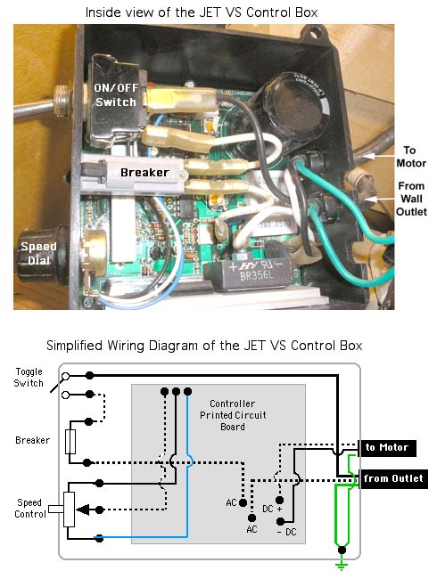
We'll start with what's inside the VS controller - a photo and a What Connects to What Diagram. You've got two power cords going into the box - one coming from a 120V AC wall outlet and one going from the PC board to the lathe's DC motor. The AC powering the controller's printed circuit board has one leg going directly to the PCB (WHITE wire) and the other (BLACK wire) to the On/Off Switch, then through a circuit breaker before connecting to the PCB. The DC wires for the motor both come off the PCB. The Controller a) converts the AC coming in to DCcoming out, using a full wave rectifier (the black box labeled BR356L). A potentiometer serves as the Speed Dial and controls the power going to the DC motor. (Probably more than you ever wanted to know but that's basically how the thing works if anyone's interested)
As you can see in the photo, all the wire connections are made with "quick disconnect" connectors (aka paddle connectors) THAT means you can plug and unplug them rather than soldering / desoldering or cutting them. And THAT means you've got UNDO if you want to return to the stock arrangement.
Now let'slook at the DPDT Center Off switch to be put in place of the stock On/Off toggle switch. Here's what it looks like. Unlike the stock toggle switch that has only two terminals, this one has SIX terminals - with screws - on the back. BTW, it's about $4 USD. You'll need to remove the screws from the terminals and file or grind of the threaded "dimples" in order to use quick disconnect wire connectors
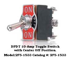
Here's how this DPDT Center Off toggle switch works.
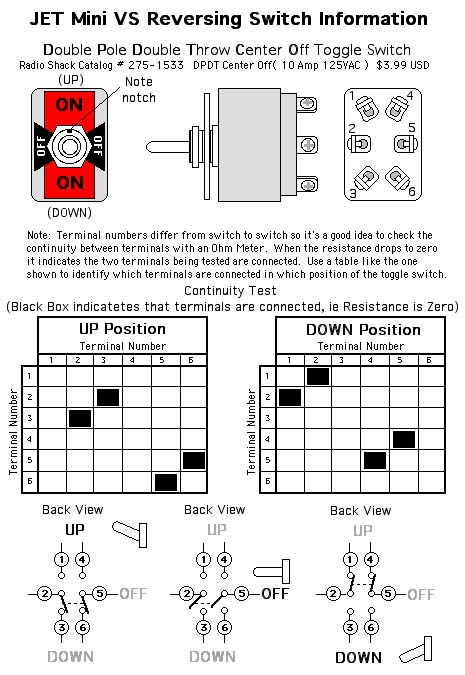
Now if we jumper / wire together terninals1 & 6 and jumper / wire together terminals 3 & 4, we can reverse the polarity of the current going to the lathe's DC motor
Here's how the DPDT Center Off switch flips the polarity ot the DC motor

The stock wiring use female quick connect connectors on the ends of wires. Handy because that lets you unplug things from one terminal and plug them backin somewhere else. We'll be adding two 16 gaugemulti-strand wires, to our controller circuit, one RED and one BLACK and we'll be using female quick disconnect connectors on them.
With all THAT out of the way, here's the Before & After diagram of What Connects To What. THIS is the image you want to download, print and keep handy while rewiring the VS Controller.